Solution Proposal for EMC
1. Introduction
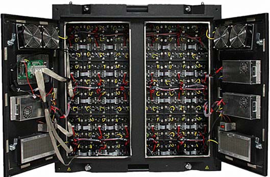
Proposal of EMC solution is to ensure that LED displays avoid electromagnetic interference under the same electromagnetic environment to reduce electronic radiation and improve the capability of interference and anti‐jamming. In this program, every LED display cabinet can be implemented according to customers’ needs.
2. Solution proposal implementation
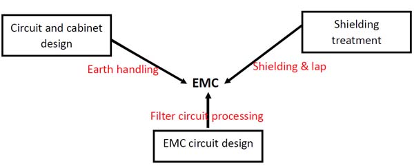
Through three aspects to reduce electronic radiation and improve the capability of interference and anti‐jamming:
1. Circuit and cabinet design to earth handling;
2. EMC circuit design, filter circuit processing;
3. Radiation shielding treatment;
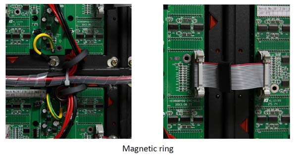
Magnetic ring
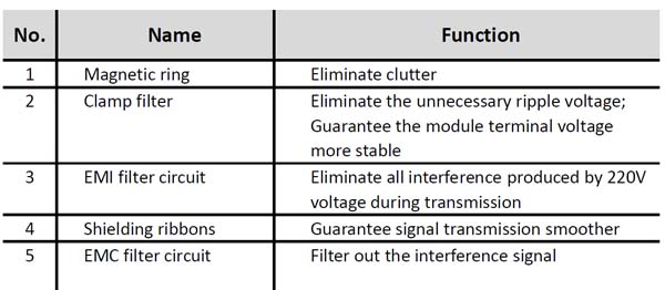
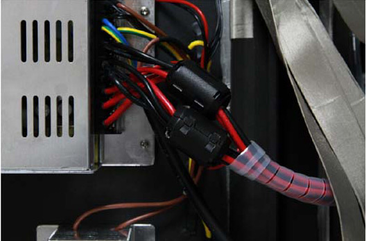
The function of modules ports plus magnetic ring is to eliminate clutter. It can eliminate the interference caused during transmission.
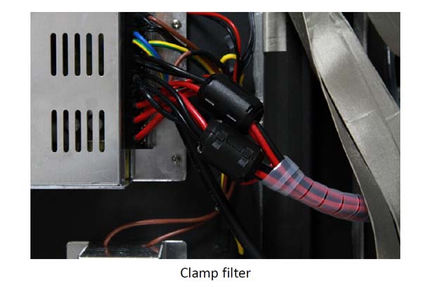
Clamp filter
The function of power supply output plus Clamp filter is to eliminate clutter. Output waveform from switching power supply is certainly not smooth DC voltage, and it will produce the unnecessary interference signal through the signal power amplifier in the transmission process. Clamp filter is to eliminate the unnecessary ripple voltage, to guarantee the module terminal voltage more stable.
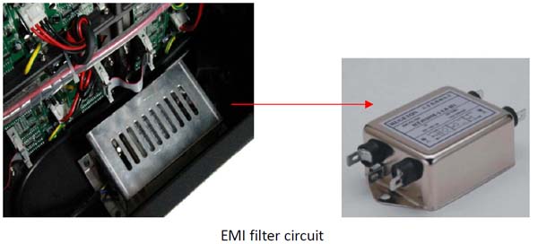
EMI filter circuit
220V power supply into the cabinet plus EMI filter circuit is to eliminate conducted interference. 220V electric power is very unstable. EMI filter circuit is to eliminate all interference produced by 220V voltage during transmission.
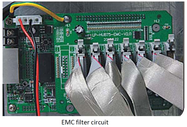
EMC filter circuit
Due to signal power amplification of wiring of HUB board, interference signals are amplified synchronously; if signals are transmitted to the module, it will generate adverse effects. Receiving card plus EMC filter circuit is to filter out the interference signal.
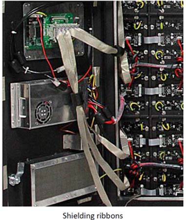
Shielding ribbons
During transmission, external signals can interfere with signals of cabinets owing to longer distance. Cables plus shielding ribbons is to prevent such a phenomenon that it interferes with other signals, other signals can not disturb it. Shielding ribbons guarantee signal transmission smoother in the transfer process.
3. EMC solution diagram
